7b-ex. Combined Loading Examples
Ex. 7b.1
Back | Index | Next

Example 7b.1

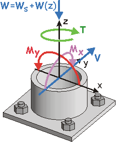
Given: Consider the road sign of Example 2b.5. The forces, moments, and torque acting at a cross-section near the base of the mast are shown and right (Cut A-A).

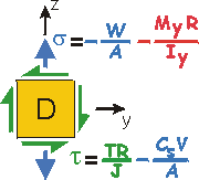
Req'd: Determine the stress states at the surface of the mast, at Points A, B, C and D. Point :
        • A is on the windward side (facing the wind),
        • C is on the "leeward side" (back side),
        • B is on the left side, and
        • D is on the right side of the mast.
Draw 2-d stress elements as you look from the outside of the mast inward.
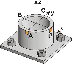
Forces, Moments and Torque acting at Cut A-A.

Road Sign

Sol'n:
Step 1. Consider the five different types of loads acting at the cross-section individually. Then, determine the stresses that each load causes, and at what points the stresses act.

Each load causes the mast to act as a different type of member, e.g.:

  • Under the torque, the mast acts as a torsion member.
  • Because of the shear force, the mast acts as a beam.
  • The weight makes it act like an axial member.

Load

Mast Acts as

Causes Stress at Surface

Torque, T

Shaft about z-axis

Shear Force, V (y-direction)

Beam about x-axis

Moment, Mx

Beam about x-axis

Moment, My

Beam about y-axis

Axial Force, W=Ws+Wm(z)

Axial Member
along z-axis


          Ix is the Moment of Inertia about the x-axis.
          Iy is the Moment of Inertia about the y-axis.


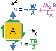
Step 2. Consider how each of the loads affects Point A.

Loads Causing Stresses at Point A.   Coordinates:   x=0, y= –R

Load

Mast Acts as

Stress Equation for Stress at Surface.

Does Pt. A "feel" this stress?

Stress that acts at Point A

Torque, T

Shaft about z-axis

Yes – entire cross-section supports torque

Shear Force, V

Beam about x-axis

No – shear stress is zero at the "top and bottom" of a beam (Points A&C) - the mast acts as a beam bending against the shear force caused by the wind

0

Moment, Mx

Beam about x-axis

Yes (tension) – bending stress is maximum at "top and bottom" of beam

Moment, My

Beam about y-axis

No – bending stress is zero at Centroidal Axis, about which beam is bending (the y-axis for My)

0

Axial Force, W=Ws+Wm(z)

Axial Member

Yes (compression) – entire cross-section supports axial load


Point A
feels three stresses:

  1. shear stress due to the torque;
  2. normal stress (tensile) due to the bending moment about the x-axis;
  3. normal stress (compressive) due to the weight.

What are the stresses at the other points?

Stress State at Pt. A


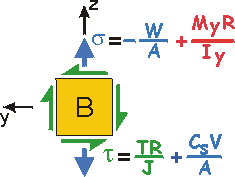
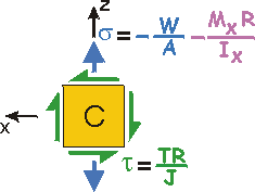
Step 3. By knowing the loads (forces, torques and moments) that occur at the cross-section, the stresses that act on the other elements can also be found:

Loads Causing Stresses:

Load

Mast Acts as

Stress Equation

Pt. A

Pt. B
Pt. C
Pt. D

Torque, T

Torsion Member about z-axis

Yes

Yes
Yes
Yes
Shear Force, V
Beam about x-axis
No
Yes
No
Yes;
opposite stress of torsion

Moment, Mx

Beam about x-axis

Yes (+)

No
Yes (–)
No

Moment, My

Beam about y-axis

No

Yes (–)
No
Yes (+)

Axial Force, W=Ws+Wm(z)

Axial Member

Yes (–)

Yes (–)
Yes(–)
Yes (–)

Notes on Normal Stresses:

  • (+) means normal stress is tensile.
  • (–) means normal stress is compressive.
  • Ix and Iy are the moments of inertia about the x- and y-axes at the centroid of the cross-section, respectively. Due to symmetry they are equal.

Notes on Shear Stresses:

  • At Point B, the Shear Stresses ADD as they are in the same direction (+y-direction);
  • At Point D, the Shear Stresses SUBTRACT - they are in opposite directions.
  • Below, Cs = (4/3)[(Ro2 + RoRi + Ri2) / (Ro2 + Ri2)]


Top Back | Index | Next

Updated: 05/21/09 DJD