Statics Online Examples
Ex. e2.1Ex. e2.2Ex. e2.3Ex. e2.4Ex. e2.5
Back | Index | Next

Example 2.2.1 Moment Equilibrium

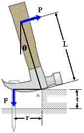
Given: In an attempt to pull a nail out of a piece of wood, force P = 20 lb is applied perpendicular to the handle of a hammer. A block is placed under the hammer to provide leverage. The hammer pivots (rocks) at Point A. Let L = 10 in., q = 15o and r = 2.0 in.

Req'd: Determine the tensile force in the nail.

Sol'n: Tensile force F can be determined by taking the FBD of the hammer and summing moments about Point A. Taking counterclockwise moments as positive:

SMA = –PL + Fr = 0

F = PL/r = [(20 lb)(10 in.)] / (2.0 in.)

F = 100 lb

Note that angle q is not needed since P is normal to the handle.


Applied force P and force of nail on hammer. What forces are missing if this is to be a correct FBD?

Example 2.2.2 Moment Equilibrium

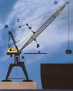
Given: A crane is used to move cargo to and from ocean-going ships. The crane is lifting an object of mass M = 1000 kg. The crane mast AD has length of LAD = 30 m, and mass of mmast = 400 kg. The mast b = 40° from the horizontal, and a = 20°. Angle ABC is a right angle.

Req'd: Determine the tension in cable CD.

Sol'n: Create a free-body diagram of the crane mast. Including the weight of the mast itself, which is assumed to act at the center of the mast.

To determine the tension TCD, sum moments about Point A.


Click Here to see the FBD

TCD = kN


Example 2.2.3 Torsion

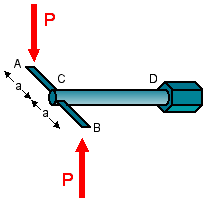
Given: Specifications for a particular lug-nut on a car require that the nut be tightened to a torque of 150 ft-lb.

Req'd: Determine the force P needed to obtain the required torque. Let a = 9 in.

Sol'n: The forces P at the ends of the wrench arms cause a resultant torque at Point C of TC = P(2a).

From a free-body diagram of the shaft CD, the torque at C must equal the torque at D. Therefore:

TC = TD

P(2a) = 150 lb-ft

P = 150 lb-ft / (18 in.) = 150 lb-ft / (1.5 ft)

P = 100 lb


Lug Wrench


FBD of lug wrench shaft.

Example 2.2.4 Beam

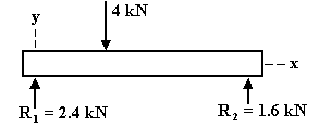
Given: The I-beam shown at right is acted upon by a 4 kN point load 4 m from the left end.

Req'd: Determine the shear force and bending moment distributions throughout the beam. Plot the results on Shear and Moment Diagrams.

Sol'n: From the FBD of the entire beam, the reaction forces at the supports are found by taking moments about each end:

SMx=0 = 0 –(4 kN)(4 m) + R2(10 m) = 0
SMx=10 = 0 (4 kN)(6 m) – R1(10 m) = 0

R1 = 2.4 kN    R2 = 1.6 kN

Check: SFy= 2.4 kN + 1.6 kN – 4 kN = 0    OK

A segment of the beam of length x (0< x < 4 m) is next isolated and treated as a FBD. The internal shear force and bending moment acting on the segment are shown in their positive directions (per this text).

Applying equilibrium:

S Fy = 0 2.4 + V(x) = 0
V(x) = –2.4 kN

S M = 0 M(x) – 2.4x = 0
M(x) = 2.4x kN·m

These internal loads act on any cross-section of the beam to the left of the 4 kN load (x<4m).


A segment of the beam to the right of the 4-kN load is next isolated in a similar manner. Equilibrium gives:

S Fy = 0 V(x) = 1.6 kN

S M = 0 M(x) = 1.6(10 – x) kN·m

These internal loads act on any cross-section of the beam to the right of the point load (x>4m).


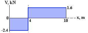
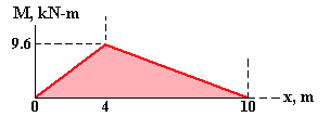
V(x) and M(x) can be plotted on Shear Force and Bending Moment Diagrams.

  • Between R1 and the 4-kN point load, the internal shear force has a constant value of –2.4 kN (the negative sign indicates the shear force acts downward on a positive x-face, opposite drawn). To the right of the point load the shear force has a value of +1.6 kN.
  • From x = 0 to 4 m, the bending moment increases linearly from of 0 to 9.6 kN·m. To the right of the load, the bending moment decreases linearly from 9.6 kN·m to 0.

The change in moment between two cross-sections is the negative in area under the shear diagram. From 0 to 4 m: Area = (2.4 N)(4 m) = 9.6 kN·m].

Beams are covered in more depth in Chapter 6.


FBD of entire beam


FBDs of segments of the beam
left: for x < 4m; right: for x > 4m. Positive sense of shear force and moment per convention of text.


Shear diagram


Moment diagram


Shear and Moment Equations


Example 2.2.5 Combined Loading

Given: A 14' by 8' road sign hangs over Hwy 101 near UCSB. The bottom of the sign is 20 ft above the roadway. The weight of the sign is 300 lb, the weight of the supporting framework is 600 lb, and the weight of the mast is 2000 lb. During a storm the wind pressure applies an equivalent force of 2200 lb acting at the center of the sign.

Req'd: Determine the reaction forces and moments at the base of the sign.


Sol'n
:
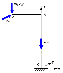
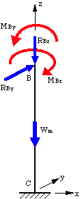
Step 1: The first step is to create a FBD of the sign/support/mast system. The weight of the sign Ws, the weight of the supporting framework Wf, and the wind force Fw, all act through the center of the sign at Point A, while the weight of the mast Wm, acts along the axis of the mast BC.


Applied forces

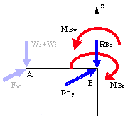
Step 2: The forces acting at A can be relocated to B, creating force-couple systems at B:

  • RBy = Fw = 2200 lb
    MBz = Fw[(14 ft)/2] = 15400 lb-ft
  • RBz = Ws + Wf = 900 lb
    MBy = (Ws + Wf)[(14 ft)/2] = 6300 lb-ft


Step 3:
Apply equilibrium on mast BC to determine the reaction forces and moments. The reactions are drawn in the positive direction of the coordinate axes.

SFx = 0 :  RCx = 0

SFy = 0 :  RCy + RBy = 0 :   RCy = -2200 lb

SFz = 0 :  RCz = RBz + Wm = 2900 lb

SMx = 0 :  MCx = RBy(20' + 4') = 52800 lb-ft

SMy = 0 :  MCy = MBy = 6300 lb-ft

SMz = 0 :  MCz = MBz = 15400 lb-ft

Note that the moment about the z-axis Mz, is generally referred to as a torque since it twists the mast as if it were a torsion member. Here, torque on the mast is constant throughout BC.


Applied Forces

Top Back | Index | Next

Updated: 02/15/09